
Okay, let me walk you through my time messing around with the ESP-12 module. It’s one of those little Wi-Fi chips you see everywhere now.
Getting Started
So, I got a few of these ESP-12 modules, I think they were the ‘E’ or ‘F’ version, pretty cheap. First thing I realized, looking at this tiny thing, was you can’t just stick it onto a breadboard. The pins are these little pads along the edge, spaced really close together. Not beginner-friendly like a NodeMCU board.
My first step was figuring out how to actually connect wires to it. I ended up buying some simple adapter PCBs. These little boards basically just break out the ESP-12 pins to standard 0.1-inch headers that do fit on a breadboard or can have jumper wires plugged in easily. Soldering the ESP-12 module onto the adapter wasn’t too bad, just needed a reasonably fine soldering iron tip and a steady hand. Tack down a corner pin first, check alignment, then do the opposite corner, and finally solder the rest. Made life way easier.
Wiring It Up
Alright, with the module on an adapter, next was connecting it to my computer to program it. You need a USB-to-serial converter for this. I used one based on the CP2102 chip, but an FTDI one works just the same. Here’s the basic hookup I did:
- Power: This is super important. The ESP-12 needs 3.3 Volts. Do NOT connect it to 5V, you’ll likely fry it. I learned that the hard way once. So, 3.3V from the serial adapter to the VCC pin on the ESP-12 adapter board.
- Ground: Connect the GND pin from the serial adapter to the GND pin on the ESP-12 board. Always need a common ground.
- Serial Communication: Connect the RX pin of the serial adapter to the TX pin of the ESP-12, and the TX pin of the adapter to the RX pin of the ESP-12. They need to cross over like that to talk to each other.
There are a couple of other pins you need to handle:
- CH_PD (or EN): This is the Chip Enable pin. It needs to be pulled HIGH (connected to 3.3V) for the chip to run. I usually just tied it directly to the 3.3V line.
- RST (Reset): Good practice to have this connected so you can reset the chip. I often connect it to GND through a momentary push button, leaving it floating or pulled HIGH otherwise.
- GPIO15: This one needs to be pulled LOW (connected to GND) for the chip to boot correctly. Usually used a 10k resistor to ground for this.
Programming Mode – The Tricky Bit
Now, to upload code, you gotta put the ESP-12 into programming mode. This involves the GPIO0 pin. Here’s the routine I got into:
- Connect GPIO0 to GND. I just used a jumper wire for this.
- Make sure all the other connections (power, ground, serial, CH_PD, GPIO15) are correct.
- Apply power or press the reset button while GPIO0 is still connected to GND.
- Now the chip is waiting for new code. You can remove the jumper wire from GPIO0 after programming starts, or just leave it until it’s done flashing.
It felt a bit clunky at first, holding a wire while plugging things in or hitting reset, but you get used to it.
Uploading Code
I used the Arduino IDE because I was already familiar with it. First time, I had to go into File -> Preferences and add the ESP8266 board manager URL. Found that online easily enough. Then went to Tools -> Board -> Boards Manager, searched for ‘esp8266’ and installed it.
After that, I selected the right board under Tools -> Board. Usually ‘Generic ESP8266 Module’ works fine for a bare ESP-12. I made sure to select the correct COM port that my USB-to-serial adapter showed up as under Tools -> Port.
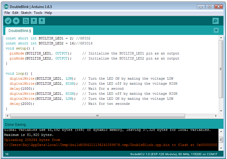
I started with a simple test: making the onboard LED blink. On most ESP-12E/F modules, the blue LED is connected to GPIO2. So I loaded the basic `Blink` example from the Arduino IDE menus and just changed the `LED_BUILTIN` pin number to `2`.
Then, the moment of truth: Put the board in programming mode (GPIO0 to GND, then reset/power on), hit the ‘Upload’ button in the Arduino IDE. Watched the messages at the bottom. Sometimes it failed, usually a connection issue or wrong COM port. But when it worked, you see the progress bar fill up.
Seeing it Work
Once the upload finished, I needed to get it out of programming mode to run the actual code. So, I disconnected the jumper wire between GPIO0 and GND. Then I pressed the reset button (or just unplugged and replugged the power). And boom! The little blue LED on the module started blinking. Success!
After blinking an LED, the next step was obviously getting it on Wi-Fi. I used the standard `ESP8266WiFi` library examples included with the Arduino core. Modified one to connect to my home network and print the IP address it got to the Serial Monitor. Opened the Serial Monitor in the Arduino IDE (making sure the baud rate matched what was in my code, usually 115200), reset the board, and watched it connect and print the IP. Pretty cool.
Final Thoughts
Working directly with an ESP-12 module definitely takes more setup than using something like a Wemos D1 Mini or a NodeMCU, which have the USB port, voltage regulator, and boot mode buttons built right in. You have to handle the power, the serial connection, and the boot mode pins yourself. But, once you get past that initial hurdle, it’s just a powerful little ESP8266 chip. It’s great when you want something really small for a project, or if you’re making a lot of something and want to keep the cost down. It was a good learning experience, figuring out the bare minimum needed to get one of these things running.